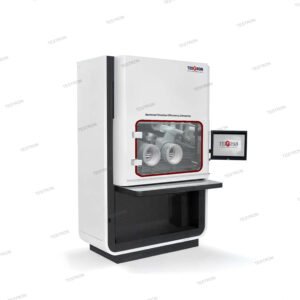
Application of TT-OFT Optical Fiber Cable Tensile Testing Machine
This measuring method applies to optical fiber cables, which are tested at tensile strength to examine the behavior of the attenuation and the fiber elongation strain as a function of the load on a cable, which may occur during installation and/or operation.
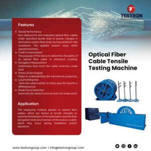
Features of TT-OFT Optical Fiber Cable Tensile Testing Machine
Tensile Performance
Non-destructive test evaluates optical fiber cables under specified tensile load to assess changes in attenuation and/or fiber strain during installation-like conditions. The applied tension stays within operational limits.
Crush (Compression)
The purpose of this test is to determine the ability of an optical fiber cable to withstand crushing.
Elongation Measurement
Determines how much the cable stretches under load.
Stress-Strain Analysis
Helps in understanding the mechanical properties.
Load Holding Test
Tests the cable’s ability to hold a specific load for a defined period.
Break Force Detection
Automatically detects and records the break point.
Technical Specifications of TT-OFT Optical Fiber Cable Tensile Testing Machine
| Model | TT-OFT Optical Fiber Cable Tensile Testing Machine |
| Load Capacity | 50kN, 100kN, 150kN, 200kN |
| Accuracy class | ±0.5% |
| Measuring range | 0.4%-100% |
| Compression head | 100mm×100mm hardness: HB240 280 |
| Loading speed | 0.2-500mm/min |
| Deformation measuring accuracy | ±0.5% |
| Displacement measuring accuracy | ±0.3% |
| Elongation measurement | Gauge length: 1000mm |
| Measuring resolution is better than 10μm | |
| Accuracy is better than ±0.5%. | |
| Crosshead travel | 800 – 1100mm |
Load Measurement Accuracy
±0.5% of reading to 1/100 of load weighing system capacity meets or exceeds the requirements of the following standards: ISO 7500-1, EN 10002-2, ASTM E4, JIS B7721.
Strain Measurement Accuracy
±0.5% of reading to 1/50 of full scale with most ASTM E83 class B or ISO 9513 class 0.5 extensometers meets or exceeds ASTM E83, ISO 9513, and EN 10002-4.
Speed Accuracy
Set speed 0.05% Max. Speed: ±1%
Set speed ≥0.05% Max. Speed: ±0.5%.
Position measurement accuracy
±0.01% of reading or 0.0001mm, whichever is greater
Power supply
Standard optional voltages 220/240VAC, 50-60 Hz, Power must be free of spikes and surges exceeding 10% of the nominal voltage.
Humidity Range
10% to 90% non-condensing.
Storage Temperature
-40 to +66°C (-40 to +150°F)
| Sample | Apparatus | Procedure | Pass/Fail Criteria |
| The cable length under test is 150 meters, Additional cable length is needed to connect the fibers to be tester.
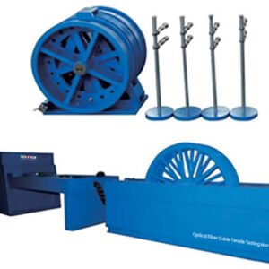
| ➣An attenuation measuring apparatus, typically an OTDR ➣A fiber elongation strain measuring apparatus based on dispersion testing equipment ➣ A specially designed tensile test machine capable of tensioning 150 meters of optical cable in six legs of 25 meters each. The machine is equipped with a motor for controlled tensioning and a load cell for measuring the actual tension applied on the cable.
| The cable is wound in the machine over appropriately sized sheaves. The cable ends extend to reach the measuring instruments. A pre-determined number of fibers within the cable are concatenated by fusion splicing. Typically, two sets of fibers are used, one will serve to measure attenuation change and the other serves for elongation monitoring. After all initial measurements and calibration are carried out, the cable is pulled at a specified rate until a pre-determined tension is applied. The cable is laid to rest under tension as per detail specifications, and then the attenuation and fiber length are measured. This process may involve several tensile levels to characterize the entire tensile behavior of the cable or be carried out only at the defined maximum allowed tension level.
| Under load, the fiber attenuation is not increased more than a predetermined value, typically 0.05dB over fiber length measured. Under load, the fiber does elongation by more than a pre-determined value over its initial length. The allowed elongation under installation load is typically 0.25%.
|
| The purpose of this test is to determine the ability of an optical fiber cable to withstand compression.
| The apparatus allows a sample cable to be crushed between a flat steel base plate and a moveable 100 mm long steel plate. The edges of the moveable plate are rounded with a radius of about 5 mm | ➣ The cable sample is mounted between the plates so that lateral movement is prevented, and a pre-determined force is applied gradually. The maximum applied force is typically maintained for 10 minutes. ➣ two types of measurements may be defined. ➣ The fiber attenuation is measured at the end of the 10-minute period while the cable is still under pressure. ➣ The fiber attenuation is measured 5 minutes after pressure. This requirement is usually carried out at higher compressive loads than the previously described measurement.
| The attenuation must not change by more than pre-determined value, typically 0.05dB. In all cases, the cable elements should not fracture or crack. Signs of compression are not considered as damage to the cable elements.
|
Load Frame of TT-OFT Optical Fiber Cable Tensile Testing Machine
| Stiff Frame | Servo Controlled Drive System |
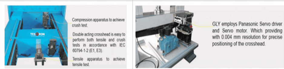 | |
| Pre-loaded and precision ball screws, a thick crosshead and base beam, and low-stretch drive belts contribute to better performance by producing more accurate modulus and strain values and minimizing the energy stored during the testPre-loaded and precision ball screws, a thick crosshead and base beam, and low-stretch drive belts contribute to better performance by producing more accurate modulus and strain values and minimizing the energy stored during the test | Along with a powerful motor, the GLY drive system consists of a rugged steel casting with a dual-belt drive system. The dual-belt system provides synchronous movement of the ball screws, eliminating crosshead tilt and aiding system alignment. |